Maintaining and repairing outdoor equipment requires a clear understanding of its individual components. Knowing how each part works together ensures the longevity and proper functioning of the machine. This section provides a closer look at the essential elements that make up your tool, helping you troubleshoot, replace, or upgrade specific sections as needed.
Identifying individual elements in your equipment can sometimes be challenging without a visual reference. A clear and detailed illustration of each piece offers a convenient way to recognize the parts and understand their specific roles. By referring to this guide, users can enhance their familiarity with the structure, ensuring they are equipped for any maintenance or repair task.
Effective maintenance starts with knowing the key pieces of the equipment. Whether you’re looking to replace a worn-out component or assemble your device correctly, recognizing the different sections is a critical step toward keeping your machine in top condition. This guide will provide the clarity you need to address any potential issues with ease.
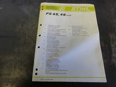
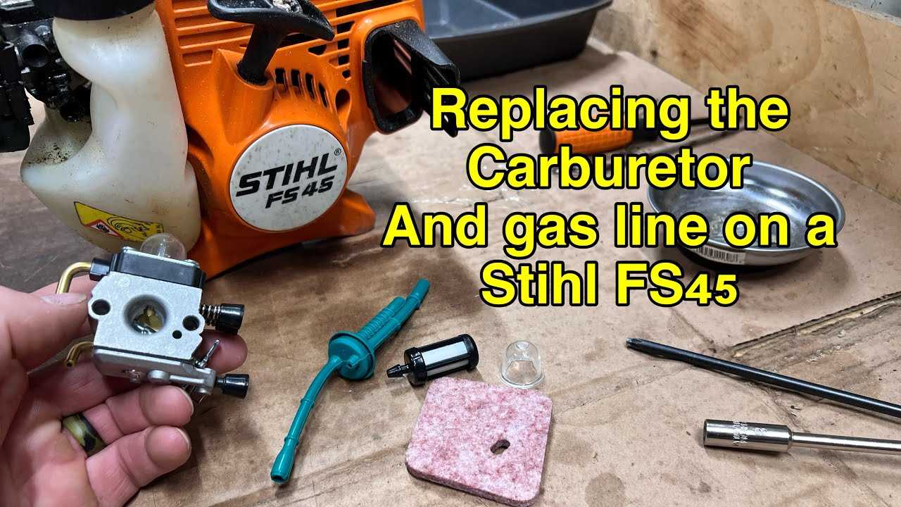
Stihl FS 45 Component Overview
Understanding the different elements of your equipment is essential for effective operation and maintenance. Each section plays a crucial role in how the tool functions, and knowing these components allows for easy identification when repairs or replacements are necessary. This section will provide an overview of the key parts that make up your device, helping you recognize them and understand their purpose.
Major Sections of the Tool

- Engine and Power Unit: The core of the machine responsible for converting fuel into energy.
- Handlebar Assembly: Provides control and maneuverability during operation.
- Cutting Mechanism: The rotating parts responsible for trimming or cutting the material.
- Fuel System: Ensures proper fuel delivery to the engine for efficient functioning.
Key Functions of Each Section
The power unit is the heart of the equipment, converting energy from the fuel into mechanical movement. The handlebar assembly allows the user to control the device and maintain comfort during use. The cutting mechanism varies depending on the model but is crucial for the tool’s ability to trim efficiently. Lastly, the fuel system ensures the engine receives the necessary fuel for operation, enabling the tool to run smoothly.
Understanding the Key Parts of FS 45
Familiarity with the key elements of your equipment is crucial for efficient operation and proper maintenance. Each section plays a specific role in the overall performance, and recognizing their function can help prevent issues while also ensuring smooth operation. In this section, we will explore the most important components and their contributions to the tool’s performance.
Main Structural Components
- Power Unit: Provides the energy necessary for the entire system to function effectively.
- Handle and Grip: Allows the user to control the tool and ensures stability during operation.
- Transmission: Transmits energy from the power unit to the cutting mechanism.
- Cutting Head: The mechanism that performs the cutting or trimming tasks with precision.
Additional Supporting Elements
- Fuel Tank: Stores the fuel needed to power the engine.
- Safety Features: Includes mechanisms to ensure user protection during operation.
- Maintenance Access Points: Areas designed for easy servicing and part replacement.
Each part in the system plays a vital role, and understanding them will help users to perform better maintenance, troubleshooting, and repairs when necessary. Recognizing these components is the first step toward enhancing the performance and longevity of your equipment.
How to Use the Parts Diagram Effectively
Using a visual reference to identify the components of your equipment is an essential tool for efficient maintenance and repairs. A clear illustration allows users to recognize each element and understand its function within the system. By following the guide, you can pinpoint issues quickly, locate replacement parts, and perform repairs with confidence.
To maximize the effectiveness of the visual guide, start by familiarizing yourself with the layout. Identify the main sections and their relationships to one another. This will help you understand the flow of energy and the roles each component plays. Pay attention to numbered labels or color coding, as these can provide additional clarity for locating specific pieces.
Once you’ve gained a basic understanding, use the guide to troubleshoot or plan maintenance tasks. If you’re unsure of how a part fits or operates, consult the reference to ensure accuracy. Whether you’re replacing a worn-out piece or assembling the tool, the visual reference simplifies the process and ensures all components are correctly installed and functioning.