Maintaining farm equipment requires a clear understanding of its structure and individual elements. Identifying each part and knowing how they work together is essential for efficient operation and long-term durability. When working with complex machinery, having a visual reference of the layout helps simplify the maintenance process and ensure that all components are in proper condition.
Every machine has its own unique setup, and recognizing the individual roles of different pieces is key to troubleshooting, repairs, and overall performance. Whether you are replacing worn parts or conducting regular inspections, a clear overview of the components will guide you through the necessary steps.
Being able to interpret these visual aids can save time, prevent errors, and assist in making informed decisions about the equipment’s upkeep. In the following sections, we’ll explore how to decode these references and use them effectively for your machinery’s maintenance needs.
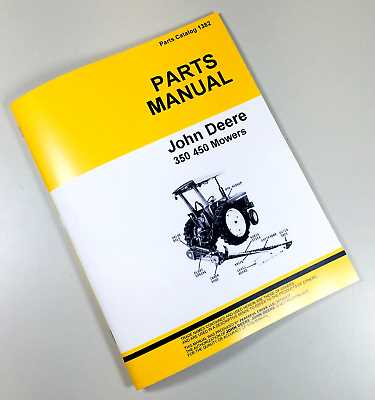
Understanding the John Deere 350 Mower
Farm machinery designed for cutting and clearing vegetation plays a vital role in ensuring efficient land management. These machines are engineered to handle heavy-duty tasks, providing reliable performance in tough agricultural environments. To maximize their potential, it’s crucial to comprehend how each component works in harmony, allowing the machine to operate smoothly and effectively.
Key Features of the Equipment
This particular model is built with durability and precision in mind. Equipped with an efficient cutting system, it offers versatility in managing different types of terrain and vegetation. The robust frame supports various attachments, ensuring that the machine can adapt to specific needs while maintaining consistent results. Understanding how the design contributes to performance is essential for keeping the machine in optimal working condition.
Maintenance Considerations
Regular upkeep is crucial to prevent wear and tear on critical components. Knowing where each part fits and how they interact will help in identifying potential issues early. This proactive approach allows for timely repairs and part replacements, minimizing downtime. Being familiar with the equipment’s layout is a key step in preserving its longevity and avoiding costly maintenance in the future.
Key Components of the Sickle Mower
For effective operation, understanding the core elements that make up agricultural equipment is crucial. Each section of the machine has a specific role that contributes to its overall functionality, ensuring smooth and efficient performance. Familiarity with these individual components helps in maintaining the equipment and preventing potential issues during usage.
Cutting Mechanism
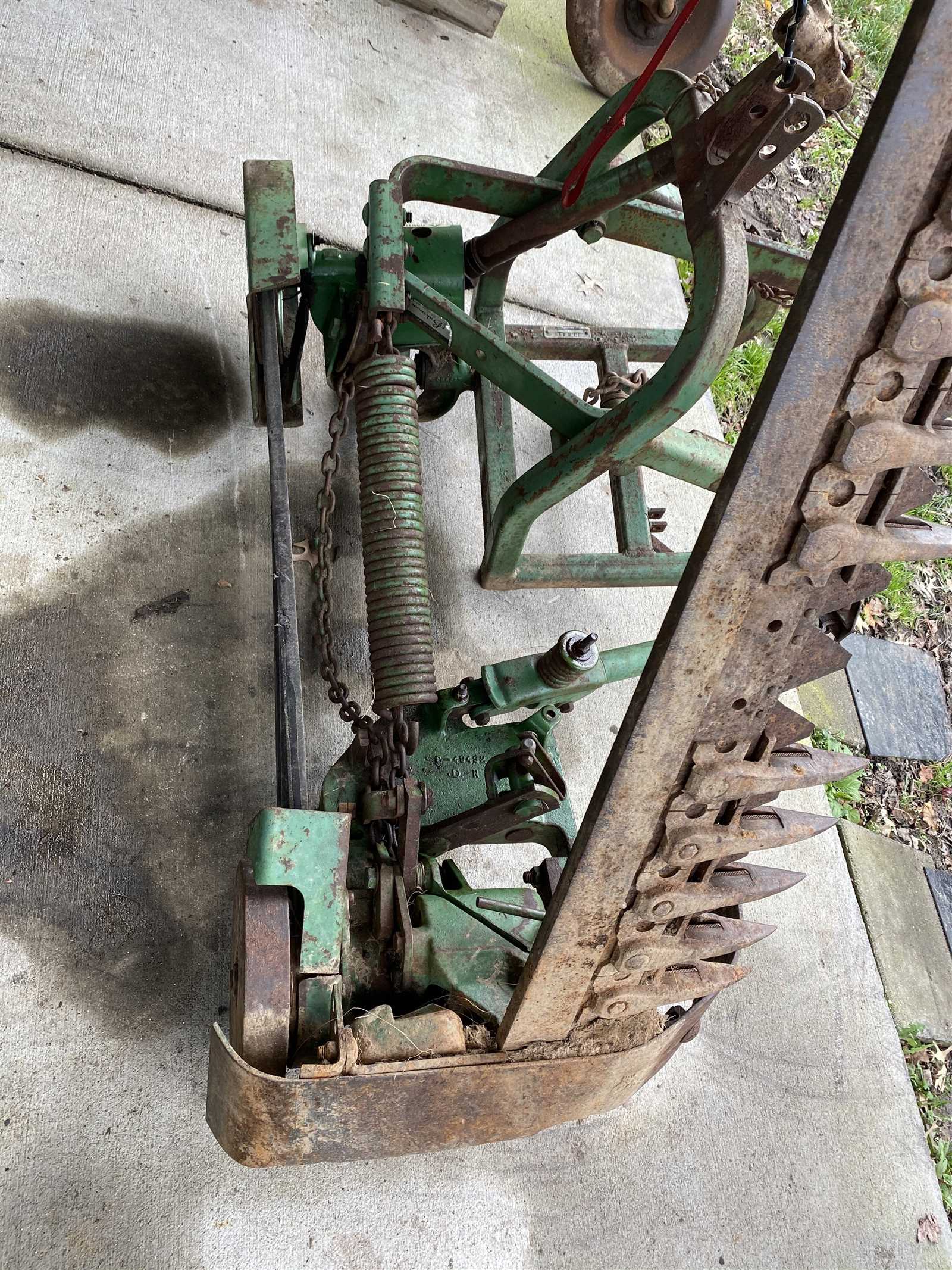
The cutting mechanism is the heart of the machine, responsible for clearing vegetation quickly and precisely. This system includes sharp blades that move back and forth, designed to slice through plant material with minimal resistance. Ensuring that these elements are well-maintained is vital for achieving a clean cut and reducing strain on the engine.
Drive and Support System
The drive and support system connects the motor to the moving components, allowing for efficient power transmission. This system includes pulleys, belts, and shafts that must be regularly inspected to avoid wear. Proper lubrication and alignment are essential for maintaining the flow of energy throughout the machine, ensuring smooth operation during use.
How to Read the Parts Diagram
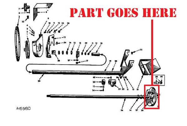
Understanding visual representations of machinery is essential for efficient maintenance and repairs. A detailed illustration of a machine’s components can provide valuable insights into its structure, allowing you to identify specific pieces and understand their functions. By properly interpreting these visual guides, you can ensure the right steps are taken during upkeep.
To begin, look for labels or numbers assigned to each part. These markers typically correspond to a list that provides further information about the component, such as its function, material, or replacement instructions. Carefully study the layout to understand how different sections are connected and how their movements contribute to the overall performance.
Pay attention to the orientation of parts in the diagram. Some diagrams may show exploded views, where parts are arranged as if they’ve been separated, which helps visualize how they fit together. This is particularly helpful when disassembling or reassembling the equipment, as it guides you through the process step by step.