Every vehicle relies on a complex network of interconnected components that work together to ensure smooth operation. Among these, the mechanism responsible for delivering the essential liquid to the engine is vital. The system consists of several crucial elements, each playing a specific role in maintaining efficiency and performance. Understanding the function of each part helps in diagnosing issues and ensuring the system works as intended.
Each component, from the central unit to the smallest connector, has its distinct purpose. By examining their layout and connections, it becomes easier to identify potential sources of malfunction. Recognizing how these elements work together can save both time and resources when addressing performance problems.
Detailed representations of these elements provide valuable insight into their design and interaction. Knowing how to interpret these visuals can enhance one’s ability to troubleshoot and maintain the system effectively. Understanding these components at a deeper level is essential for anyone working with or maintaining modern engines.
Fuel Pump Key Components Explained

At the heart of every modern engine’s operation lies a carefully crafted system responsible for transferring vital liquid to the engine. This system is made up of several critical components, each designed to function seamlessly together. Understanding each element’s role provides clarity on how they contribute to the overall efficiency and performance.
The central unit, often considered the core of this assembly, ensures the proper flow and pressure of the liquid. Surrounding it are several smaller, yet equally important, components like the filter, which keeps contaminants out, and the regulator, which maintains consistent pressure throughout the system. Each of these parts works in tandem to ensure a steady, uninterrupted flow to the engine.
The connectors that link all these components are just as important, as they ensure everything stays in place and functions correctly. Without the right seals and connections, the system would fail to operate efficiently. Regular maintenance of these crucial elements ensures longevity and peak performance, preventing costly repairs down the road.
Common Fuel Pump Part Functions
The system responsible for liquid delivery consists of several key components, each performing a specific role to ensure smooth operation. Each part serves a unique function that contributes to the overall efficiency, making it essential to understand how these elements interact. Without proper understanding, issues can arise that might impede performance.
The central unit is designed to control the flow of the liquid, maintaining the necessary pressure for efficient engine function. Another crucial element is the filter, which prevents any foreign particles from entering and potentially damaging the system. The regulator plays its part by ensuring consistent pressure, adjusting to varying demands as needed.
The connectors and seals ensure that all components remain securely in place, maintaining the integrity of the entire assembly. Without these, leaks and malfunctions would occur, significantly affecting performance. Understanding how each component functions individually and together helps in identifying potential issues and maintaining the system in top condition.
How to Read a Fuel Pump Diagram
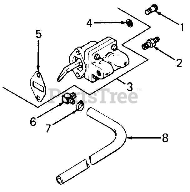
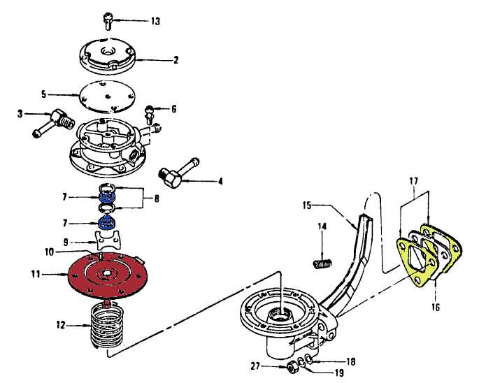
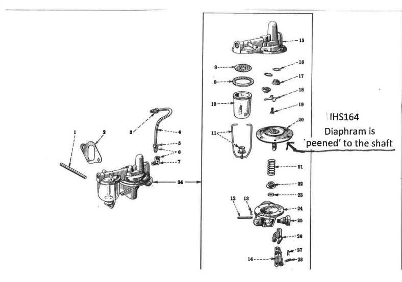
Understanding a technical representation of the delivery system can be a valuable skill when troubleshooting or performing maintenance. These visual guides provide a detailed layout of the components, showing how each element is connected and how they work together. Interpreting these images correctly can save time and help pinpoint issues.
Key Elements in a Diagram

When reading a visual map of the system, it’s important to recognize the core components and their positions. Here’s what to look for:
- Connections: Lines and arrows often indicate how parts are linked and where liquids or gases travel.
- Labels: Most diagrams will have labels to identify each component, making it easier to understand their function.
- Symbols: Certain icons represent specific parts such as regulators, filters, and valves. Recognizing these symbols is key to interpreting the diagram correctly.
Step-by-Step Approach to Reading
To effectively read the diagram, follow these steps:
- Start by identifying the main components and understanding their basic functions.
- Next, trace the connections between parts to understand how they interact with one another.
- Pay attention to any flow directions or pressure indicators that help explain the system’s behavior under different conditions.
- Finally, cross-reference the diagram with the system’s manual to confirm the correct interpretation and component placement.