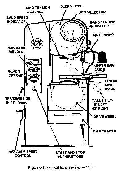
In the world of precision cutting, understanding the different components of machinery is crucial for effective operation and maintenance. Each tool consists of several distinct elements that work together to achieve accurate results. Familiarity with these elements helps improve performance and ensures safety during use.
Comprehending the layout of each piece is essential for troubleshooting and repairs. Knowing what each part does and how it contributes to the whole system is beneficial for both new users and experienced operators. Whether you are assembling or maintaining the machine, an in-depth knowledge of its structure is invaluable.
Identifying the function of each section will help you optimize the tool’s capabilities. A clear understanding of the internal workings will also assist in proper adjustments and prolong the lifespan of the equipment.
Understanding the Components of a Cutting Machine
The operation of any advanced cutting tool relies on a variety of essential elements, each contributing to its efficiency and precision. By gaining an understanding of how these components work together, users can ensure smoother operation and improved performance. These elements are carefully designed to support the overall functioning of the equipment, making maintenance and repairs easier for users at all levels.
Core Elements of the System
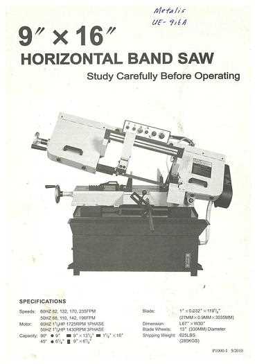
At the heart of every machine lies a set of primary components that perform specific tasks. These include the motor, drive mechanism, and the guiding systems, all of which are responsible for the power and direction of the cutting process. Without a clear understanding of these core parts, it can be difficult to diagnose issues or optimize performance.
Supporting Mechanisms for Efficiency
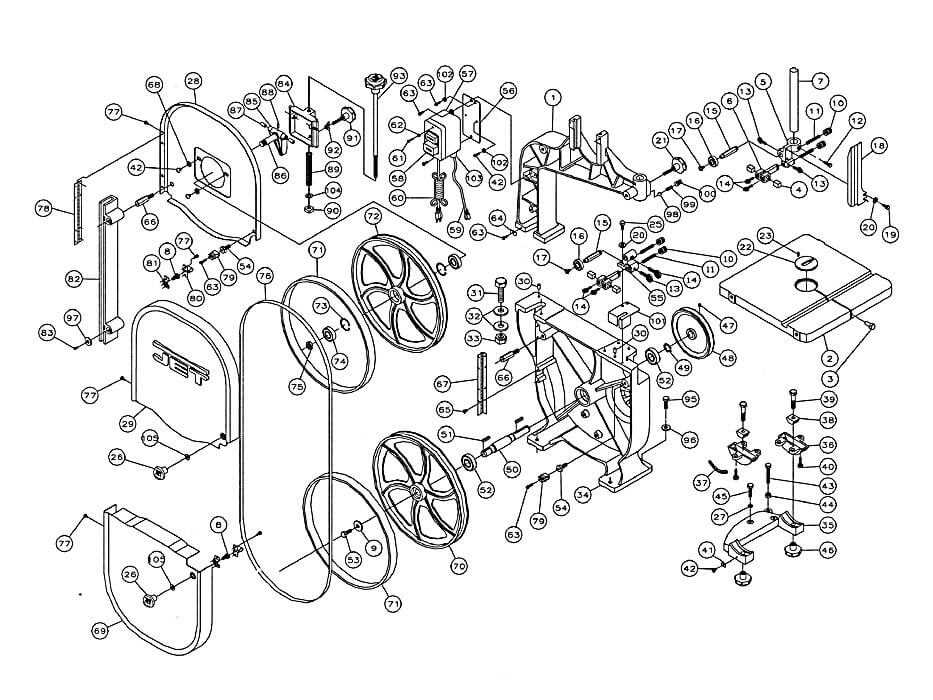
Along with the primary elements, there are several auxiliary mechanisms that play a crucial role in maintaining consistent operation. These include tensioning systems, lubrication devices, and the frame structure, which all work in unison to maintain stability and ensure smooth cutting actions. A solid grasp of these supporting components is vital for keeping the equipment in top working condition.
Key Parts of a Cutting Machine
To achieve precision and reliability, every cutting tool is made up of several integral components that must work together seamlessly. Each element serves a distinct purpose, ensuring that the machine performs at its best. Understanding the role of each component is essential for effective operation, maintenance, and troubleshooting.
Power and Movement Mechanisms
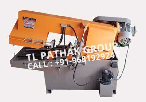
The motor and drive system are fundamental to the operation of any cutting device. These components provide the necessary force to drive the cutting mechanism and enable the tool to cut through materials. A well-maintained power source ensures smooth and consistent operation over time.
Guiding and Tensioning Systems
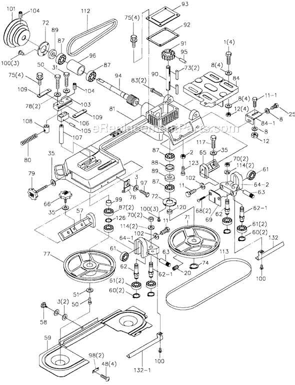
Another critical set of elements are the guiding and tensioning systems, which ensure the cutting mechanism stays aligned and operates with optimal stability. Proper tension is essential for maintaining accuracy, while the guide rails keep the tool steady during use. Regular inspection of these components is crucial to prevent inaccuracies or wear.
How to Identify Cutting Tool Components in Diagrams
Understanding the layout of a cutting machine through a schematic representation is crucial for anyone looking to perform maintenance or repairs. Diagrams help visualize the arrangement of various elements and their interactions within the system. By familiarizing yourself with these visuals, identifying and troubleshooting issues becomes much easier.
When reviewing such illustrations, it’s important to focus on key visual indicators. The most common components will typically be highlighted or labeled for quick reference. Here’s how to recognize the most important parts:
- Frame: Usually depicted as the main structure supporting the tool, often rectangular or square.
- Motor: Typically shown at the base or side of the machine, often with lines representing power connections.
- Guiding Elements: These components are typically shown as rails or tracks that the cutting mechanism follows.
- Tensioning Mechanism: Usually represented by spring-like shapes or adjustable mechanisms near the cutting component.
By focusing on these features and becoming familiar with common diagram styles, users can quickly identify individual elements and their functions in any system schematic.