Maintaining and repairing outdoor tools requires a solid understanding of their internal structure. Knowing how each part interacts ensures smooth operation and efficient troubleshooting. This guide provides a detailed look at key components of a garden machine.
Identifying each section of the equipment and its purpose allows for easier maintenance and part replacement. A clear understanding of how everything fits together will help in identifying potential issues and understanding the assembly process.
In-depth exploration of the main components can help users prevent common malfunctions. By recognizing the function of each element, it becomes easier to determine when and why certain parts might need attention or replacement.
Understanding Stihl RB 400 Components
Every mechanical device relies on a set of individual elements working together seamlessly. In outdoor machinery, each component plays a vital role in ensuring performance, durability, and ease of operation. A closer examination of these components is crucial for proper care and maintenance, allowing users to identify and address issues before they affect functionality.
Main Structure of the Equipment
The main framework houses all the essential systems, providing the foundation for the machine. Understanding the core structure allows users to locate other components and observe their interaction. Key sections typically include the motor housing, control system, and drive mechanisms, each contributing to the overall efficiency.
Functional Elements and Their Roles

Each functional part has a specific task that contributes to the overall operation. For instance, drive mechanisms help transfer power, while control systems regulate speed and movement. Identifying these components helps in troubleshooting and optimizing the performance of the equipment, ensuring a long-lasting and reliable service life.
How to Read Stihl RB 400 Diagram
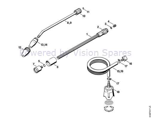
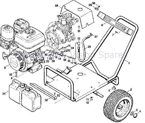
Understanding technical illustrations is essential for anyone working with mechanical equipment. These visuals provide a clear and organized representation of the machine’s structure, helping users identify various components and their connections. Knowing how to interpret these illustrations allows for easier repairs and maintenance.
Interpreting the Layout

The diagram is typically divided into sections that highlight different parts of the machine. Each section is labeled to indicate specific areas such as the engine or the drive system. By following the flow of the illustration, users can easily identify the position of each component relative to the whole structure.
Identifying Key Components
In addition to the layout, diagrams often include symbols or numbers that correspond to specific parts. This system makes it easier to find replacements or recognize where issues may arise. Understanding these markers is essential for ensuring proper repairs and maintenance.
Common Parts and Their Functions

In any mechanical device, certain components are critical to its smooth operation. These elements work in tandem, ensuring the machine functions properly and efficiently. Understanding the role of each part helps with maintenance and troubleshooting, making it easier to keep everything running smoothly.
Drive Mechanism
The drive system is responsible for transferring power from the engine to the working parts of the machine. This mechanism ensures that the machine performs its intended tasks with optimal force and speed. Regular inspection of this component can prevent performance issues and mechanical failure.
Control System
The control system regulates the operation of the machine. By adjusting speed and direction, it allows users to control the movement and behavior of the equipment. This system is crucial for achieving precise results and minimizing wear on other components.